


load-break disconnector switches are designed for low-load breaking overhead MV electrical lines. Equipped with an air-break technology system combined with an isolating switch in series, this device provides visible opening and great safety in operation.
Category: Switchgear & High Voltage LBS
Brand: JGGY Electric
Model: ISAR-S/IACM
Power: 12KV/17.5kV/24kV/36kV/ 400A/630A/1250A
FOB Port: Ningbo/Shanghai
Terms of Pyament: Western Union,T/T,Paypal
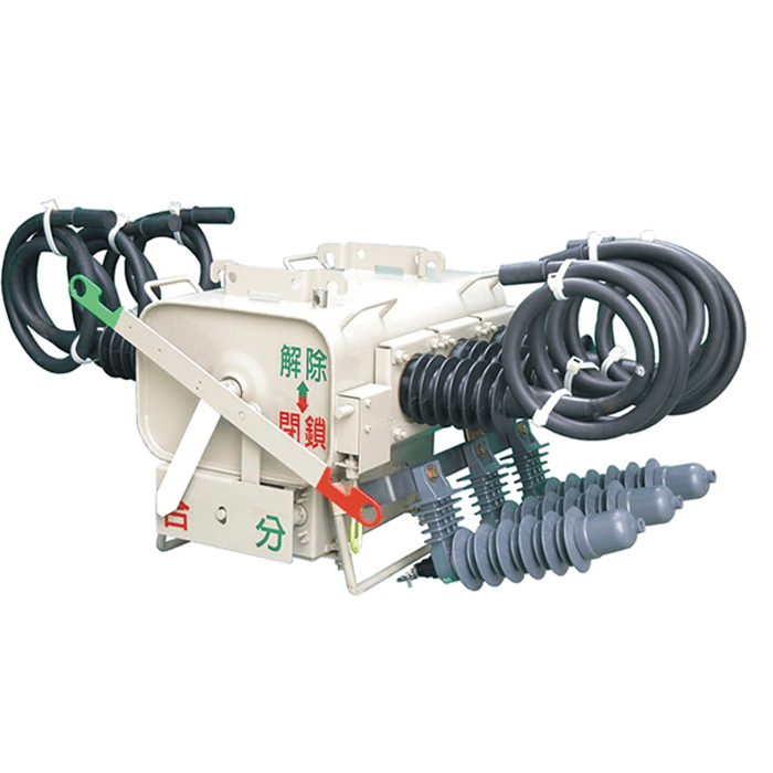
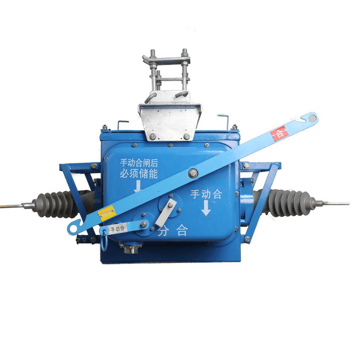
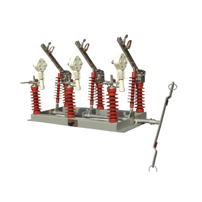
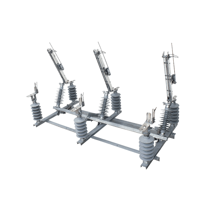
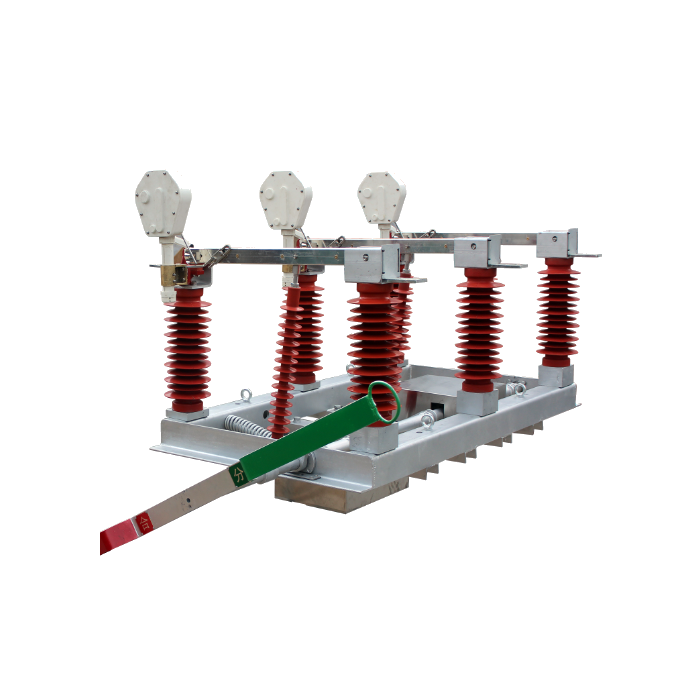
Manually Operated Overhead Switch
The IACM-12/17.5/24/36kV overhead switch, placed at the end of a line in a tree-like HVA network structure, can isolate a cluster of substations for work on the downstream line. This device complies with Type I of the NF C 64-140 standard of 01/1990.
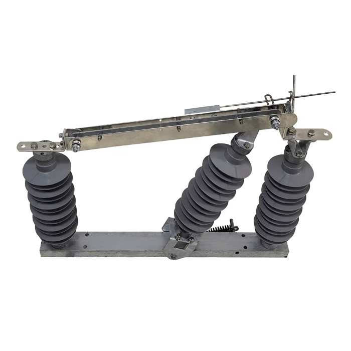
Construction Details
• Hot-dip galvanized steel profile frame compliant with the NF A 91 121 standard.
• Articulation: journaled on bronze bushing.
• Insulators: RP5 type tempered glass. Insulator rods with identical bases for all nine insulators.
• Aluminum bronze collars.
• Work-hardened copper blade driven by grease-free nylon rollers. Its C-shaped profile provides high short-circuit current resistance and reduced heating.
• Break contacts: wide penetration and alignment tolerances; permanent contact zone separate from the break contact.
• Perfect visibility of the "open" position. All live parts are stainless steel.
• Connections: 25mm diameter cylindrical aluminum pins for live working (LWT).
• Whip-type disconnect devices.
• Trumbler-type spring-loaded snap-closing device, acting directly on the moving shaft without driving the actuator, which only initiates movement.
• Elastic shaft stops at the end of travel.
• Support brackets made up of two symmetrical welded and galvanized profile elements, allowing the switch to be clamped to any support with head dimensions between 100 and 360 mm.
• Phase-insulating support for bird protection.
Mechanical control: It is designed to be secured to a corner of the support using a strap. It consists of:
• a lockable control lever with insulation;
• a lower tube with insulation;
• two telescopic tubes adjustable to approximately 300 mm, allowing it to be adapted to supports from 11 to 14 m;
• three roller tube guides (one tube and one tube guide can be supplied as an extra with supports from 15 to 18 m).
NO. | ltem | Unit | Data | ||||
1 | Rated voltage | KV | 12 | 17.5 | 24 | 36 | |
2 | Rated current | A | 200/400/630/1250 | ||||
3 | Rated active load breaking current | A | 50 | 50 | 50 | 50 | |
4 | Rated No-load transformer breaking current | A | 2.5 | 2.5 | 2.5 | 2.5 | |
5 | Rated No-load line breaking capacity | A | 10 | 10 | 10 | 10 | |
6 |
1min power frequency withstand voltage | phase to phase, to earth | KV | 42 | 45 | 55 | 95 |
across open contacts | KV | 48 | 55 | 69 | 105 | ||
7 |
Lightning impulse withstand voltage | phase to phase, to earth | KV | 75 | 95 | 125 | 170 |
across open contacts | KV | 85 | 105 | 145 | 195 | ||
8 | Rated short-time withstand curent | KA | 12.5 | 12.5 | 12.5 | 12.5 | |
9 | Rated short-circuit duration | S | 1 | 1 | 1 | 1 | |
10 | Rated peak withstand current | KA | 31.5 | 31.5 | 31.5 | 31.5 | |
11 |
Mechanical life | Times | 2000 | 2000 | 2000 | 2000 | |
12 | Manual operating torque | Nm | ≤200 | ≤200 | ≤200 | ≤200 | |
13 | Contact opening distance | mm | >500 | >60 | >800 | >1030 | |
14 | The position of the contact just closed is skewed | mm | >2/3 | >2/3 | >2/3 | >2/3 | |
15 | Contact pressure | N | 200 | 200 | 200 | 200 | |
16 | Three phase closing at different stages | mm | <3 | <3 | <3 | <3 | |
17 | Distance between charged bodies and relative ground | mm | >160 | >200 | >260 | >330 | |
18 | Main loop resistance | uΩ | ≤150 | ≤150 | ≤150 | ≤150 | |
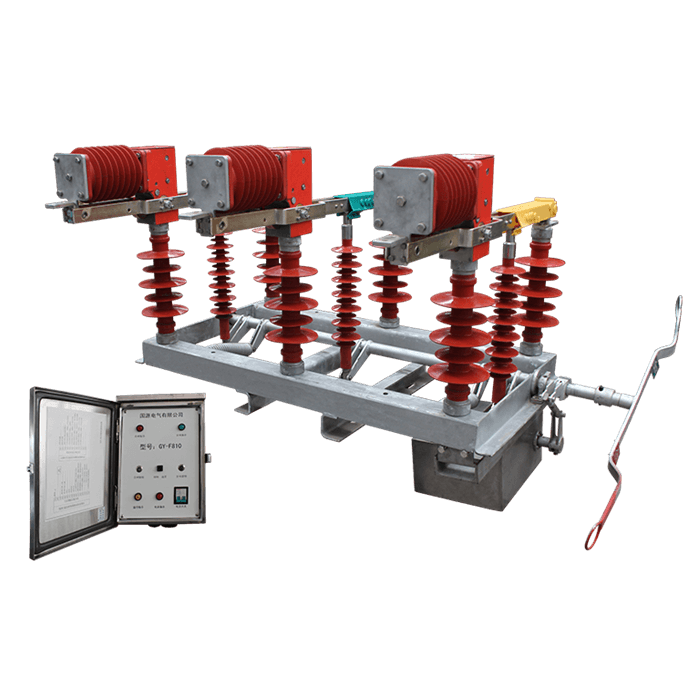
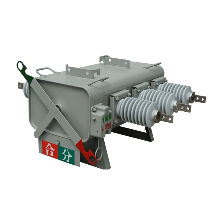
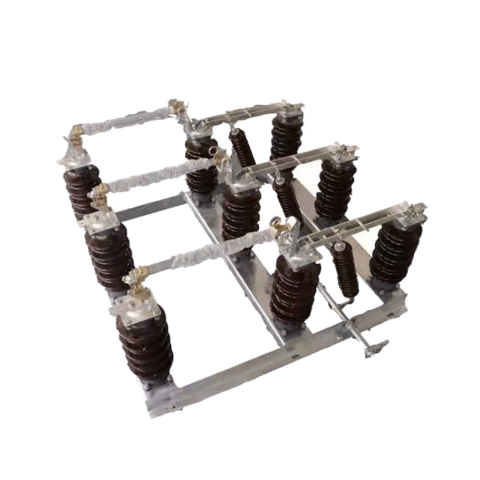
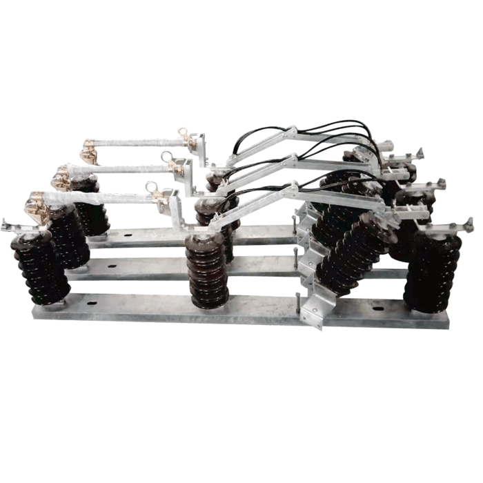
24KV LBS with three-phase linkage, is mainly consist of frame, vacuum interrupter components, disconnector components and spring mechanism, disconnector and vacuum interrupter are fixed on frame via insulator, spring is fixed on frame.
rubber split bushing - molded cable outlet
36-40KV outdoor LBS AC high voltage disconnect vacuum load break switch
outdoor SF6 LBS sectionalizer insulated load break switch, ceramic bushing - molded cable outlet
Outdoor Pole-mounted SF6 gas insulated load break switch LBS ceramic bushing
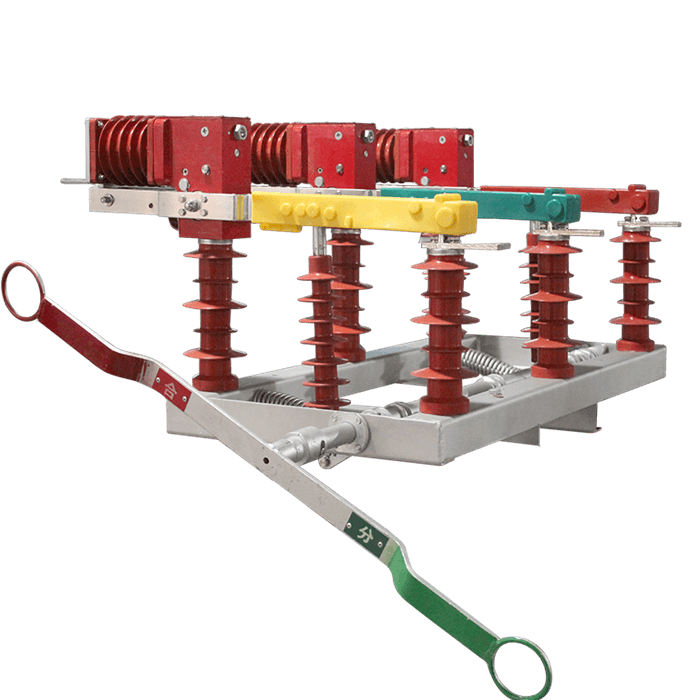
It composed of disconnector, vacuum interrupter and operating mechanism and other parts.
FW9-24 Outdoor Off-Load overhead line disconnecting switch load break switch
for outdoor three-phase AC power distribution system with rated voltage of 12kV and rated frequency of 50HZ, as opening and closing load current and closing short-circuit current
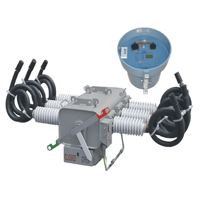
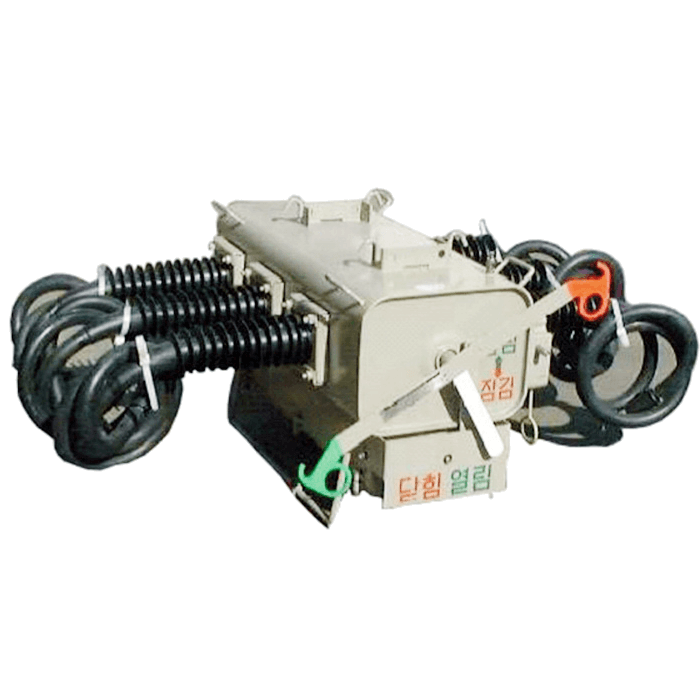
FKW18-12 Outdoor load break switch is used in outdoor 12/24/40.5kV three phase AC 50/60Hz power system, it composed of disconnect blade, arc extinguishing chamber and operating mechanism.
12KV LBS Outdoor disconnector air load break switch with cutout fuse, with strong arcing ability, reliable performance, long service life
Outdoor SF6 LBS sectionalizer load break switch, rubber bushing -terminal outlet
12KV MV Outdoor Off-Load overhead line isolator disconnector LBS load break switch
ISAR-S load-break disconnector switches Air-break overhead disconnect switch Outdoor
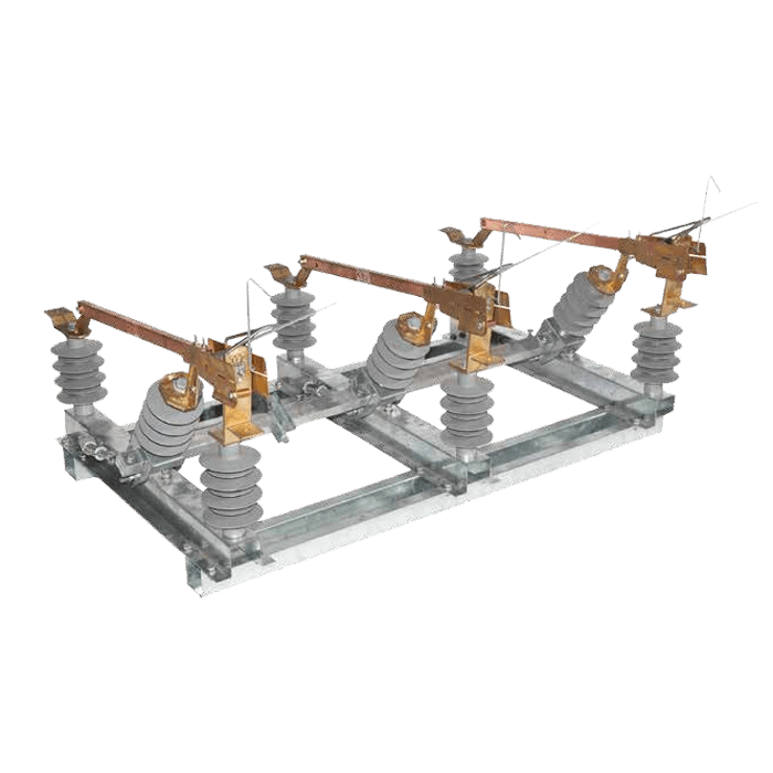
Outdoor Switch-disconnector IACM LBS-12~36/400-50 Air-break overhead load-break switches
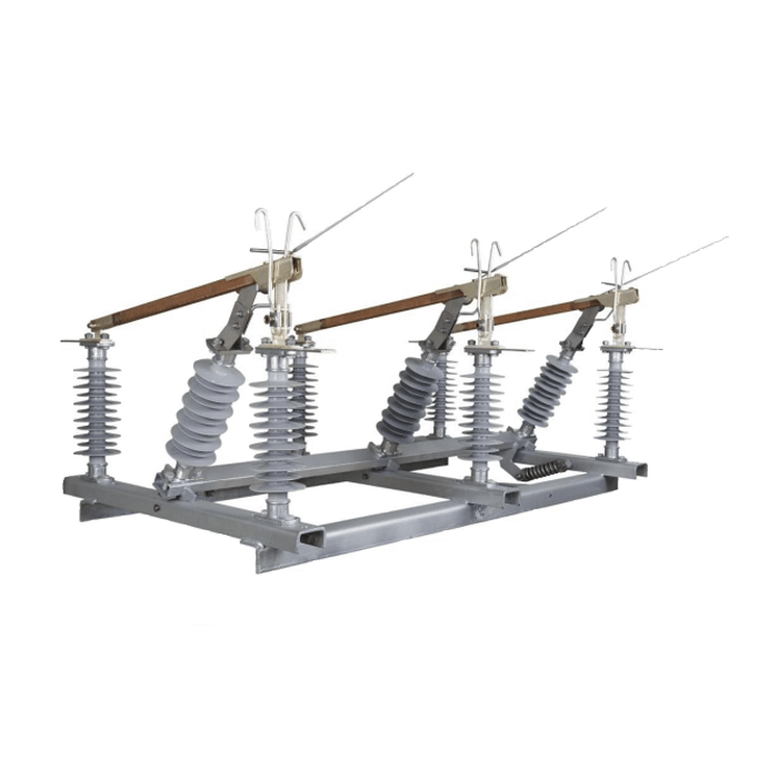
17.5kV Outdoor overhead switch IA1CM Switch-disconnector disconnecting air break LBS
IACM (Manually Operated Overhead Switch): This is a switch located on overhead power lines that is physically operated by a person, generally to isolate or restore a section of the line. It is used for maintenance or troubleshooting operations where human intervention is required.
outdoor AC high voltage isolate switch (hereinafter referred to as load break switch)
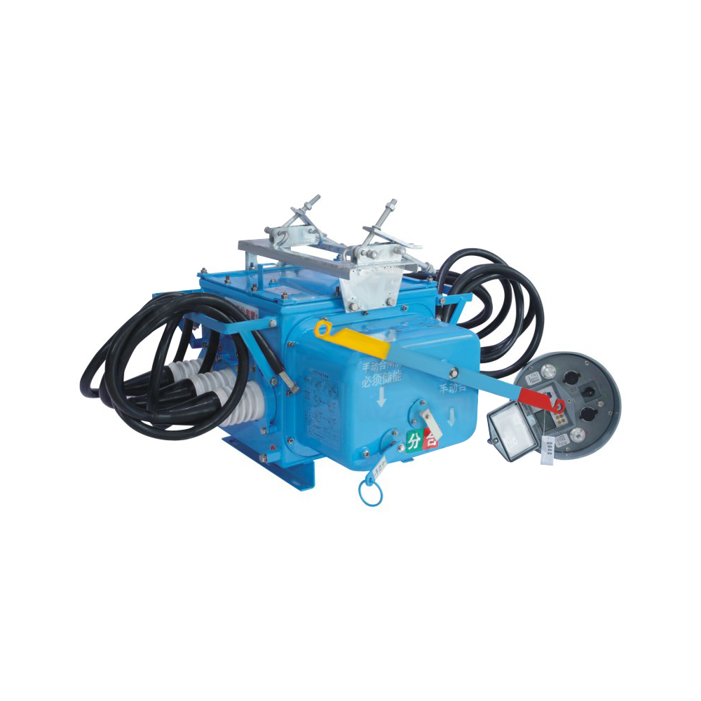
FZW28-12 series outdoor AC high-voltage boundary vacuum load switch is suitable for outdoor three-phase AC power distribution systems with a rated voltage of 12KV and a rated frequency of 50Hz. It is used to open and close load currents and close short-circuit currents.

Copyright © 2021 By JGGY Electrical.com